- #5 volt dc motors arduino how to
- #5 volt dc motors arduino driver
- #5 volt dc motors arduino code
- #5 volt dc motors arduino download
#5 volt dc motors arduino code
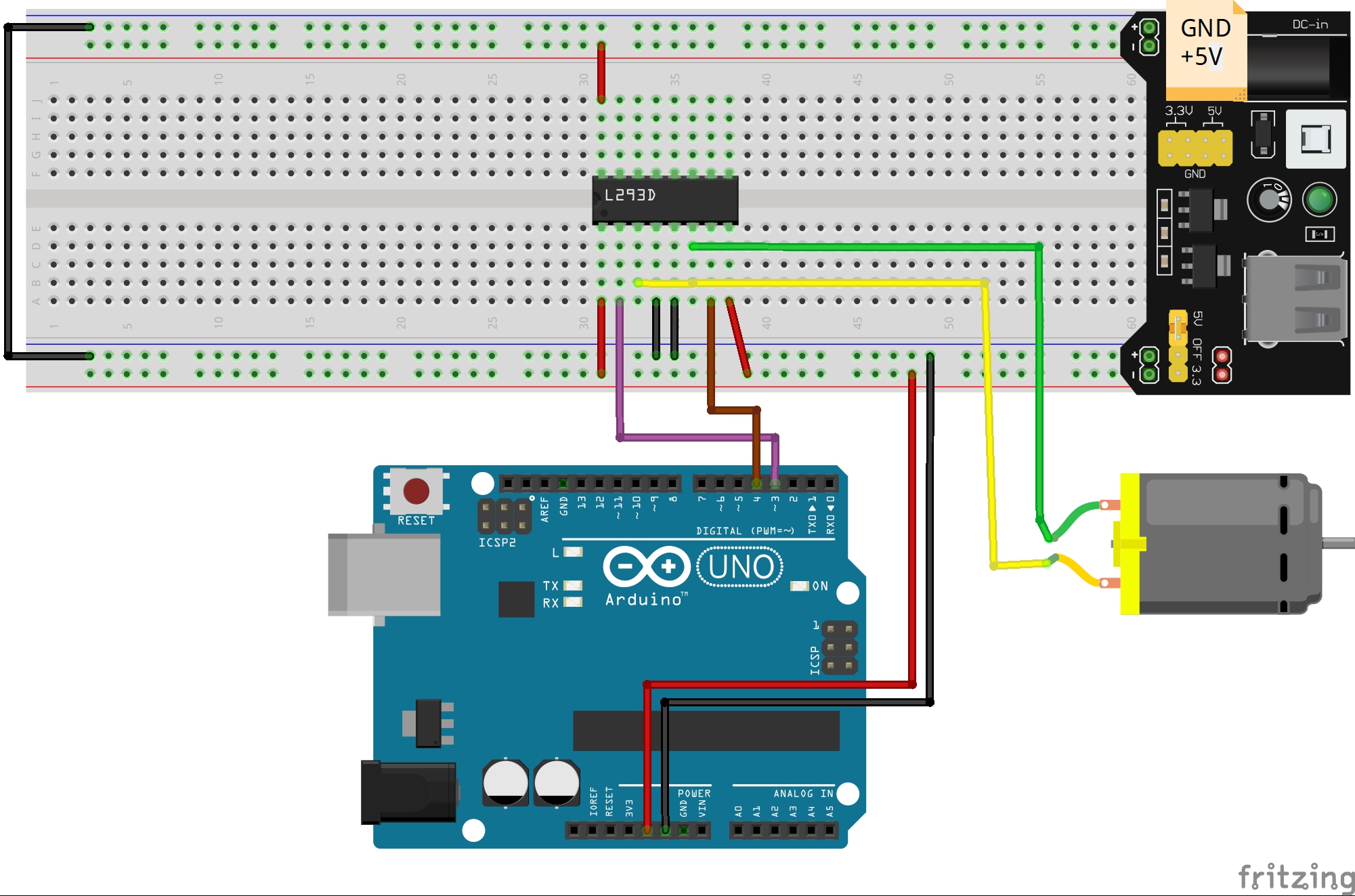
OutputĪfter the connection you will copy and paste this code in Arduino IDE than upload the code.
#5 volt dc motors arduino driver
Tutorial by RoboIndia on Motor Control using PWM Signals //Hardware Required: Motor Driver (By RoboIndia & Arduino) //Motor A const int inputPin1 = 10 // Pin 15 of L293D IC const int inputPin2 = 11 // Pin 10 of L293D IC //Motor B const int inputPin3 = 9 // Pin 7 of L293D IC const int inputPin4 = 8 // Pin 2 of L293D IC int EN1 = 5 // Pin 1 of L293D IC int EN2 = 6 // Pin 9 of L293D IC void setup ( ) 4.


#5 volt dc motors arduino download
You may download this code (Arduino Sketch) from here. If we connect these pins to ground, then the motor will get disabled. Make sure to remove the Jumper preset on Enable pins of module, so that we can connect PWM input to this pin and control the speed of motors. Module VSS power Screw terminal- External power source of 9V. Module Motor Screw terminals – DC motors.ġ0. Pin 16: VCC, for supply power to IC i.e 5V.ĩ. Pin 15: Input 3, when this pin is HIGH the current will flow though output 3. Pin 14: Output 3, this pin is connected with one terminal of motor. Pin 11: Output 4, this pin is connected with one terminal of motor. Pin 10: Input 4, when this pin is HIGH the current will flow though output 4. Pin 9: When Enable 3/4 is HIGH, Right part of IC will work, i.e motor connected with pin 11 and pin 14 will rotate. Pin 8: VSS, this pin is used to give power supply to connected motors from 5V to 36V maximum depends on Motor connected. Pin 7: Input 2, when this pin is HIGH the current will flow though output 2. Pin 6: Output 2, this pin is connected with one terminal of motor. Pin 3: Outputt 1, this pin is connected with one terminal of motor. Pin 2: Input 1, when this pin is HIGH the current will flow though output 1. Pin 1: When Enable1/2 is HIGH, Left part of IC will work, i.e motor connected with pin 3 and pin 6 will rotate. There are 4 INPUT pins, 4 OUTPUT pins and 2 ENABLE pin for each motor. The L293D is a 16 pin IC, with eight pins, on each side, to controlling of two DC motor simultaneously. This Motor Driver is designed and developed based on L293D IC. The Motor Driver is a module for motors that allows you to control the working speed and direction of two motors simultaneously. In these waves frequency is same but the ON and OFF times are different. These diagram below shows the waveforms obtained as output at different voltage requirements. The PWM controller accepts the control signal and adjusts the duty cycle of the PWM signal according to the requirements. The input signals we given to PWM controller might be an analog or digital signal according to the design of the PWM controller. The Duty Cycle of this square wave is varied in order to vary the power supplied to the load. PWM signal is essentially a high frequency square wave ( typically greater than 1KHz). The speed controller PWM for a DC motor works by varying the average voltage supplied to the motor

But in practice, for changing the speed of a dc motor we cannot go on changing the supply voltage all the time. The DC motor speed in general is directly proportional to the supply voltage, so if reduce the voltage from 9 volts to 4.5 volts then our speed become half of what it originally had.
#5 volt dc motors arduino how to
As an Amazon Associate I earn from qualifying purchases.This tutorial of Robo India explains how to control the speed of DC mtor using PWM signals.


 0 kommentar(er)
